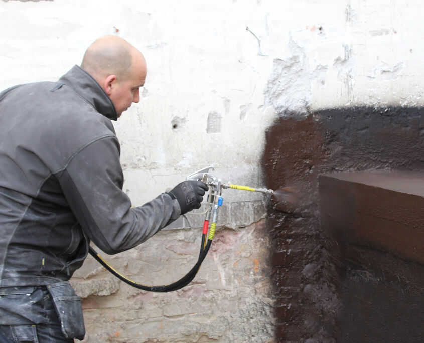
BelowGrade liquid rubber spray-applied to below-ground foundation wall
Basement, Foundation and Buried-Structure Waterproofing

Below-Ground Waterproofing Systems

One opportunity before backfill

Below-ground waterproofing is applied before the structure is buried. Once backfilled, membrane defects become inaccessible. Remediation requires excavation, disruption and costs that routinely exceed the original specification several times over.

Below-ground waterproofing protects buried and earth-retaining structures — basements, foundations, retaining walls, lift pits, plant rooms, underground car parks and podium structures — from water ingress driven by groundwater, surface water and hydrostatic pressure. System…

The Problem

Below-ground structures face waterproofing conditions that are fundamentally different from those at roof or wall level. Groundwater does not follow a seasonal dry period in the same way that roof-level moisture does. Hydrostatic pressure acts continuously against the structure and its membrane. Thermal and structural movement opens and closes construction joints repeatedly across the service life of the building. And critically — once the structure is backfilled, most of the applied membrane is permanently inaccessible. Detection of a below-ground failure typically requires internal investigation and often re-excavation. Remediation costs routinely exceed the original waterproofing budget several times over.

WATERPROOFING APPROACHES — TYPE A, TYPE B AND TYPE C

BS 8102 describes three approaches to the protection of below-ground structures from water ingress. These approaches may be used individually or in combination, depending on the structure, ground conditions, water table and the required grade of internal environment.

Type A — Barrier Protection. A waterproofing barrier is applied to the structure to resist water ingress. This includes liquid-applied membranes, sheet membranes, mastic asphalt tanking and cementitious coatings applied to the structure face. BelowGrade may form the applied barrier membrane within a Type A barrier-protection design, subject to the complete project waterproofing strategy, specification and manufacturer confirmation.

Type B — Structurally Integral Protection. The structure itself is designed and constructed as the waterproofing element — typically reinforced concrete designed to a watertight specification. Type B relies on the quality, mix design, cover, compaction, construction joint design and workmanship of the concrete. A liquid-applied product cannot substitute for or replicate Type B performance — it is a different approach, not a coating for failed Type B concrete.

Type C — Drained Protection. A cavity-drain system allows water to enter a controlled void within the building envelope and directs it to drainage or pumped collection. Type C is often used for remedial work on existing structures where external access is not available. It is a fundamentally different strategy from a barrier membrane — it manages ingress rather than excluding it.

These three approaches must not be confused. A product reference to BS 8102 does not make the product itself a complete waterproofing design. The project designer must determine the appropriate protection strategy — including whether a single approach is sufficient or whether a combination is required — before any material is specified. Maintainability, repairability and long-term access for inspection must also be considered.

STRUCTURES AND APPLICATIONS

The following below-ground structure types each have specific considerations for waterproofing design, preparation and detailing:

Basement walls (cast concrete or masonry retaining) — primary application for external positive-side membrane. Membrane applied to the retained face before backfill. All construction joints, wall-to-slab junctions, tie holes and service penetrations require specific detailing.

Basement slabs (ground-bearing or suspended) — membrane applied to the underside or blinding before slab construction, or to the top surface before screed in appropriate circumstances. Falls and drainage to sumps must be confirmed as part of the design.

Foundation walls — poured concrete or masonry foundation sections below finished ground level. Access is often limited once the superstructure commences — coordination with the construction programme is critical.

Retaining walls — free-standing or basement-forming concrete or masonry walls retaining earth. External membrane required on the retained face. Protection board required before backfilling against the retained face. Drainage layer behind the retaining face may be a structural design requirement independent of the waterproofing strategy.

Lift pits — confined, low-clearance structures below ground slab level. Geometry creates complex detailing requirements at base, wall corners and lift-guide penetrations. Access for external application may be limited.

Service pits, plant rooms and tank chambers below ground — similar to basements in structural terms; drainage and chemical environment may impose additional constraints on membrane selection.

Podium structures (buried roof decks, plaza decks and landscaped decks over structure) — combination of below-ground waterproofing and inverted-roof or trafficked-deck considerations. Protection from root penetration, drainage-board installation and imposed loading must all be addressed at design stage.

Underground car parks — ground-slab level and below. May combine Type A external waterproofing at walls with Type A or B at slab level, and a separate traffic-rated membrane at the deck surface. These are different specification requirements and must not be conflated.

Tunnels and culverts — external membrane application requires access and programme coordination with civil works. Detail requirements at construction joints are intensive.

EXTERNAL POSITIVE-SIDE WATERPROOFING

Positive-side waterproofing — the membrane applied to the face of the structure that is exposed to the water source — is the preferred approach for new-build and refurbishment work where external access is available. The membrane is placed on the water side, where hydrostatic pressure acts to press it into the substrate rather than attempting to lift it away. This gives the membrane a mechanical advantage under water pressure that negative-side (internally applied) systems do not have.

External positive-side application requires excavation access to the complete structure face to be waterproofed. Access and backfill sequencing are critical. The programme window for membrane application — between exposure of the structure face and commencement of backfilling — must be sufficient to allow full preparation, primer cure, membrane application, detail completion and protection-board installation. Shortening this window to accelerate backfill is one of the most common contributors to below-ground waterproofing failure.

A completed external membrane may be difficult or impossible to repair after backfilling. Inspection before covering is not optional — it is the last opportunity to identify and repair any defect before access is permanently lost.

Do not describe an internally applied coating or cavity-drain system as positive-side waterproofing. Positive-side means the water-face of the structure, applied before the structure is buried.

SUBSTRATE PREPARATION

Below-ground concrete and masonry substrates require preparation before membrane application. Generic preparation — a pressure wash and a coat — is insufficient in this application. Required steps include:

Sound substrate confirmation — the concrete or masonry must be structurally sound and stable. Active structural movement must be resolved before any membrane specification. Failing or friable surface material must be removed.

Laitance removal and surface profile — surface laitance (weak surface layer) must be removed by grit blasting, light scabbling or grinding to expose the aggregate face. Smooth-formed concrete is insufficiently porous for reliable adhesion without preparation.

Concrete defect repair — honeycombing (voids in the concrete from inadequate compaction), blow-holes, bug-holes, tie-rod holes and any voiding must be filled and reproofed before membrane application. The membrane cannot bridge significant voids.

Construction joint preparation — each construction joint must be identified, assessed and treated. Existing sealants must be confirmed compatible; failed sealants must be removed and replaced.

Contamination removal — release agents, shuttering oils, curing compounds, efflorescence, and any existing coatings or prior waterproofing treatments must be identified and removed. Each contaminant affects adhesion differently.

Corner preparation — internal and external arrises at wall-to-slab junctions, corners and transitions should be formed to the radius or chamfer specified in the approved build-up. Sharp right-angle arrises concentrate stress in the membrane at corners and reduce coverage thickness.

Moisture condition — the substrate moisture condition must be within the application limits for the specific product and build-up at the time of application, not at the time of survey. Below-ground substrates can gain moisture rapidly from ground conditions. A moisture check carried out days before application may not reflect the application-day condition.

Primer — primer requirements depend on the substrate type, condition and the approved build-up. Primer must not be omitted where specified.

JOINTS, PENETRATIONS AND INTERFACES

The field membrane applied to the main structure face does not, by itself, resolve the critical details. Each of the following requires specific treatment within the approved specification, confirmed against manufacturer documentation:

Construction joints — the primary leak path in below-ground concrete structures. Require reinforcement, sealant, bandage strip or specific joint detail as part of the approved build-up. Field spray alone does not resolve construction joints.

Movement joints — designed to permit relative movement between structural sections. Require an appropriate flexible joint detail that accommodates the design movement without transferring load to the membrane. A membrane bridged over an unresolved movement joint will fail at that joint.

Day joints — construction sequence discontinuities. Require treatment as construction joints.

Wall-to-slab junctions — a transition point that experiences differential movement and is typically the most water-vulnerable detail in the structure. Cannot be resolved by increasing membrane thickness.

Pipe penetrations and service ducts — each penetration represents a potential membrane discontinuity. Requires collar sealing, bonded flashing or purpose-designed sleeve as confirmed in the approved build-up.

Pile caps and ground beams — interfaces at transitions in substrate type and geometry. Require specific detailing.

Tie holes — formed by formwork tie bolts in cast concrete. Must be filled and reproofed before membrane application.

Terminations — the top and bottom edges of the membrane must be correctly terminated. An unterminated edge allows water to track behind the membrane from the edge.

Interfaces with other systems — where the below-ground membrane meets a damp-proof course, a roof waterproofing system, a drainage layer, an insulation board or another applied treatment, compatibility must be confirmed and the interface detailed in the approved specification.

PROTECTION BEFORE BACKFILLING

A completed membrane must be inspected and protected before backfilling commences. This is not an advisory step — it is a specification and warranty requirement.

Protection is required because backfill materials, drainage boards, insulation, sharp aggregate, compaction plant, reinforcement and access traffic can all damage the membrane. Damage that occurs after application and before protection is installed may not be visible after backfilling and will not be discovered until water ingress occurs — potentially years later.

The protection build-up may include: a protection board compatible with the membrane; drainage layer materials; geotextile; and insulation where specified. Each element must be confirmed compatible with the membrane and with the overall waterproofing and drainage design.

Before protection is installed, the membrane must be inspected — ideally by a qualified person — and any defects or areas of insufficient coverage identified and repaired. A photographic record of the completed membrane before protection is evidence for quality assurance and warranty purposes.

Backfilling must not commence until: membrane inspection is complete; any required repairs are made and confirmed sound; protection boards are installed; and the membrane has achieved the required cure.

Controlled backfilling means using approved fill materials, maintaining the required stand-off from the membrane face during initial lifts, and not compacting directly against the membrane without a protection layer.

DRAINAGE AND GROUNDWATER

Waterproofing and drainage are related but distinct design considerations. A below-ground membrane does not remove the need for groundwater assessment or drainage design.

Groundwater level — the seasonal high water table determines the maximum hydrostatic head on the structure and membrane. This must be established from ground investigation records, borehole data or piezometer monitoring — not from a visual inspection at a single survey date.

Hydrostatic pressure — the pressure of groundwater against the below-ground structure increases with depth. A membrane that resists hydrostatic pressure must be fully bonded to a substrate that is stable against that same pressure. Unbonded or partially bonded membranes can be displaced by hydrostatic pressure.

Temporary dewatering — on new-build projects, the excavation may be dewatered during construction. The membrane must be designed for the permanent condition (without dewatering) not only the construction condition.

Permanent land drainage — a drainage layer and perimeter drain system may be required to manage groundwater around the structure. This reduces the hydrostatic head on the membrane and is often a structural design requirement independent of the waterproofing strategy.

Sumps and pumps — below-ground drainage may be directed to a sump and pump system. Pump systems require maintenance and may fail. Where the structure cannot tolerate any flooding, pump redundancy may be required.

Drainage discharge — the drainage design must account for where collected groundwater is discharged. This is typically a civil and structural engineering matter, not a waterproofing product decision.

The membrane is one element of the below-ground waterproofing strategy. It does not replace groundwater assessment, drainage design, structural design or construction quality management.

BELOWGRADE SYSTEM

BelowGrade liquid rubber is a two-component spray-applied waterproofing membrane principally used for below-ground applications. It is cold-applied, water-based, VOC-free and solvent-free. The cured membrane is seamless, fully bonded to the substrate and permanently flexible.

The following properties are stated in or consistent with the reviewed BelowGrade TDS:

— Two-component spray-applied system. Cold spray application for field areas. Hand application (brush or roller) for detailing, penetrations and transitions. Minimum application temperature: 5°C. Substrate must be dry, unfrozen and uncontaminated. — 850% elongation to ASTM D638. The cured membrane can extend to accommodate substrate movement within the detailing limits of the approved build-up. — Membrane build: approximately 1.35 kg/m² at approximately 1 mm for an airtight seal; approximately 2.7 kg/m² for a nominal 2 mm watertight membrane. The required thickness and consumption for a specific project must be confirmed in the approved specification — these nominal figures are not automatically the requirement for every build-up or detail. — The spray reaction forms the membrane rapidly. Touch-dry is typically around one minute at 20°C. This is not full adhesion, full cure or readiness for backfilling. Full adhesion to the substrate develops within approximately 48 hours; actual timing depends on temperature and humidity. Protection and insulation installation should not be treated as permitted immediately after touch-dry — timing must be confirmed against application conditions and manufacturer guidance. — Spray application can support efficient installation across suitable prepared areas. Actual project output depends on preparation, detailing, access, environmental conditions and sequencing — not on the application rate alone. — Any warranty position is project-specific and depends on the substrate, preparation, complete system build-up, application records and manufacturer acceptance. Relevant manufacturer documentation can be reviewed as part of the project-specific specification process.

Substrates for which adhesion test data are available in the reviewed TDS include: concrete, limestone, wood, PVC, zinc and aluminium. On below-ground projects, the primary substrates are concrete and suitable masonry or mineral substrates where confirmed. Other materials — including interfaces at penetrations and transitions — must have their suitability, primer requirements and preparation confirmed per project in the approved specification. Adhesion test data do not by themselves establish that every listed material is suitable as a complete below-ground waterproofing substrate in all conditions. Substrate use, primer, preparation and interface detailing must be confirmed per project.

BelowGrade may form the applied barrier membrane within a Type A barrier-protection design under BS 8102:2022, subject to the complete project waterproofing strategy, design and specification. The product is not itself the complete design, does not independently satisfy all Type A requirements, and does not carry BS 8102 certification or product approval. The project may require more than one form of protection. A suitably qualified waterproofing designer should determine the protection strategy. Maintainability, repairability and risk must be considered.

The complete project build-up — including preparation, primer, joint detailing, membrane consumption, terminations, protection and drainage interfaces — must be confirmed in the approved project specification. BelowGrade is the field membrane component of that build-up. It is not, by itself, a complete below-ground waterproofing design.

REFURBISHMENT AND REMEDIAL WORK

New-build external waterproofing — membrane applied to the external face of the structure before backfill as part of the construction programme. This is the primary application for BelowGrade.

Existing structure with external excavation access — where excavation can be carried out to expose the existing structure face, external membrane application is possible on an existing below-ground structure. The programme must account for excavation, substrate assessment, preparation of the existing surface, any prior waterproofing removal, application, protection and re-backfilling.

Existing structure without external access — where external excavation is impractical, an external positive-side membrane cannot be applied. In this condition, the appropriate routes are: Type C cavity-drain system installed internally; internal barrier coatings where conditions permit; crack injection; or a combination of approaches. External liquid waterproofing cannot be retrofitted where excavation or access is impractical.

Localised repair — where a discrete area of a previously waterproofed structure has failed, localised repair may be possible if the failure zone is identifiable and accessible. The failure mechanism must be confirmed before repair specification.

QUALITY ASSURANCE

Below-ground waterproofing has a particularly high consequence of failure. Quality assurance must be planned, not retrospective.

Required quality assurance steps include: confirmation that the approved substrate condition has been achieved before application begins; recording of environmental conditions (temperature, humidity, substrate moisture) at the start of each application period; batch and delivery records; equipment settings for spray equipment; consumption monitoring (material used per measured area); wet-film check during application where applicable; detailed inspection of all joints, penetrations and interface details during and after application; photographic records of the applied membrane before protection is installed; inspection of any damage after protection board installation; and signed-off handover records before backfill commences.

Warranty requires full compliance. Warranty is not automatic on completion of application — it requires documented evidence of compliant installation.

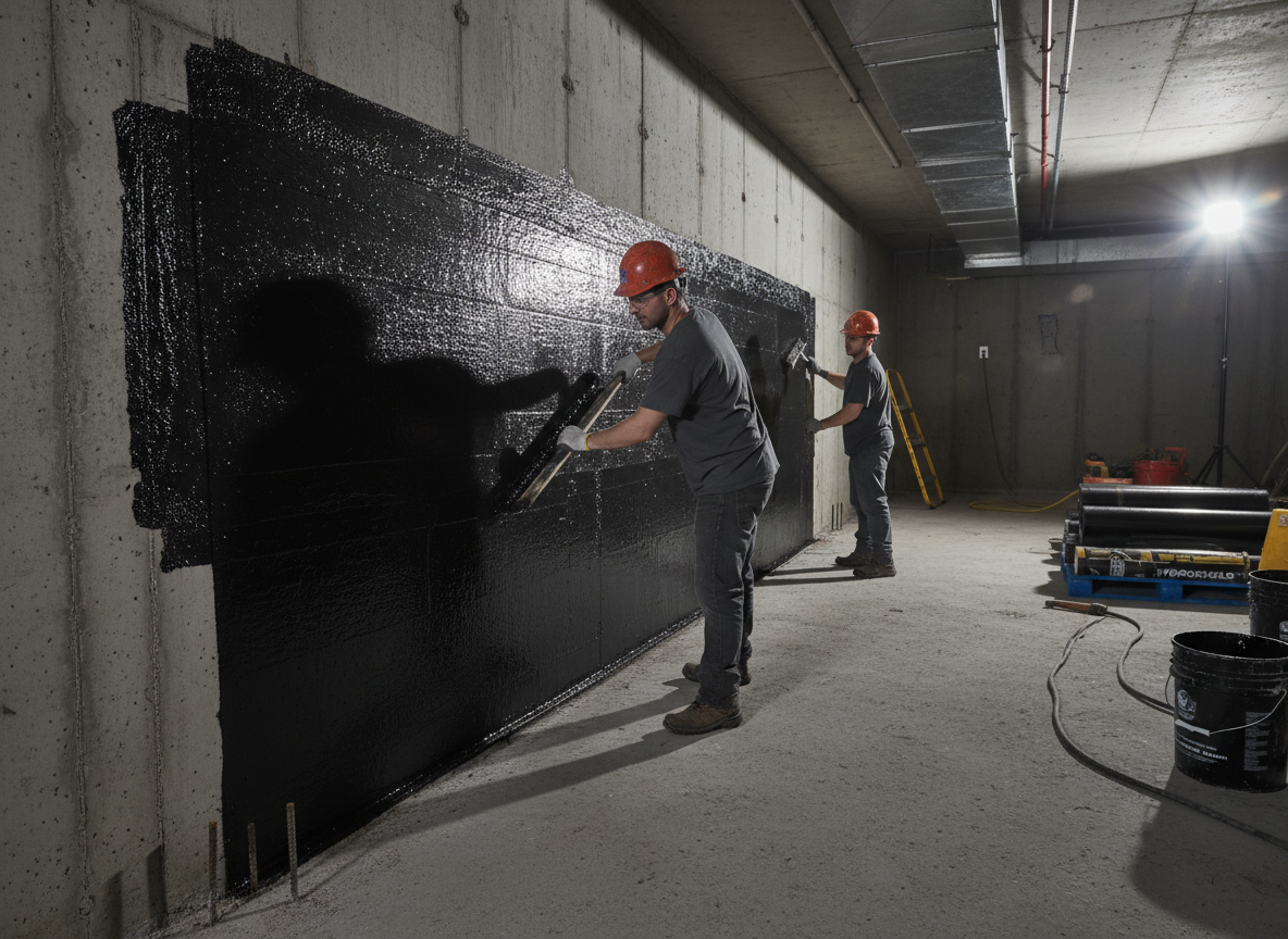
Before You Specify
  • Substrate survey required before specification — not optional
  • Application by trained approved applicators is a warranty condition
  • Coating over a failing or saturated substrate will fail — usually within a year
  • Preparation shortcuts invalidate manufacturer warranties
Applied in the Field
BelowGrade spray application to basement wall — positive-side external membrane

BelowGrade spray application to basement wall — positive-side external membrane

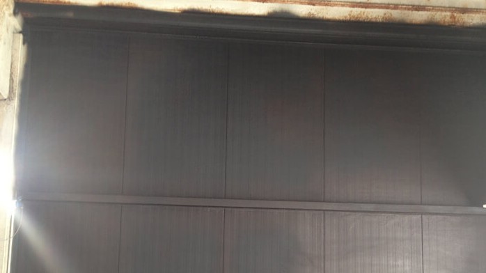
Seamless membrane on basement foundation walls — pre-backfill

Seamless membrane on basement foundation walls — pre-backfill

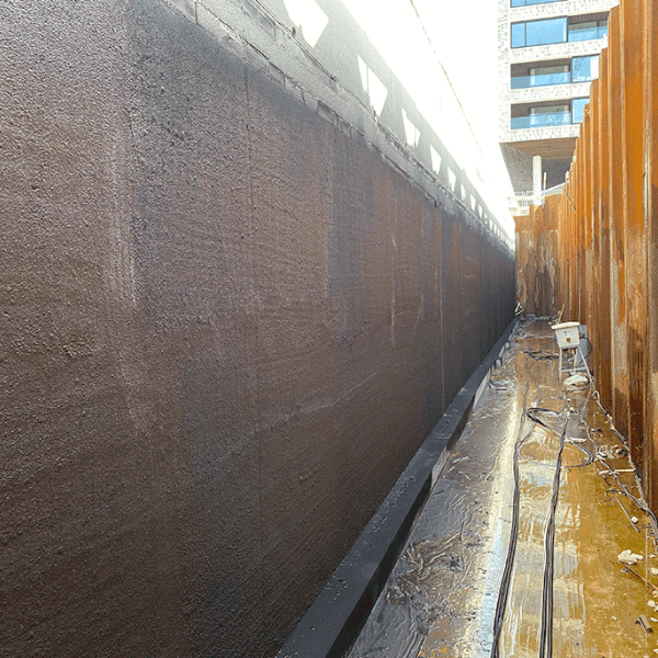
Liquid rubber applied to retaining wall — below-ground waterproofing

Liquid rubber applied to retaining wall — below-ground waterproofing

Specification Logic

What the Assessment Leads To — Below-Ground Decision Paths

Below-ground waterproofing system selection follows from the access available, the structure type, the groundwater conditions and the required protection strategy. These paths describe what different project conditions lead to.

New-build basement, foundation wall or retaining structure — external face accessible before backfill, concrete substrate sound, waterproofing required as part of construction programmeOne application window before backfill is permanent. Membrane defects that are not identified and repaired before backfilling become inaccessible. Remediation requires re-excavation.External positive-side spray-applied waterproofing membrane — seamless, fully bonded, permanently flexible, confirmed suitable for the substrate and build-upBelowGrade

Why This System Fits

BelowGrade two-component spray-applied liquid rubber membrane — cold-applied, water-based, VOC-free, solvent-free. 850% elongation to ASTM D638. Approximately 2.7 kg/m² for a nominal 2 mm watertight membrane. Touch-dry typically around one minute at 20°C — full adhesion develops within approximately 48 hours. Seamless and fully bonded to the substrate — no joints. Conforms to complex geometry at corners, construction joints and transitions. Primary substrates below ground: concrete and suitable masonry or mineral substrates where confirmed — all suitability, primer and preparation requirements confirmed per project. Spray application supports efficient installation across suitable prepared areas; actual project output depends on preparation, detailing, access, conditions and sequencing. Any warranty position is project-specific and depends on the substrate, preparation, complete system build-up, application records and manufacturer acceptance.

What Still Needs Verifying

Substrate condition must be confirmed before specification — concrete defects, honeycombing, tie holes and surface contamination require preparation and repair. Construction joint positions must be mapped and detailed within the approved build-up. Primer requirements for the specific substrate and conditions must be confirmed. Substrate moisture must be within application limits at the time of application. Protection board must be specified and installed before backfilling commences. Programme must allow sufficient time for preparation, primer cure, application, detailing, inspection and protection before backfill.

Existing below-ground structure — water ingress identified internally, external access not available, structure already buriedExternal membrane application is not possible without excavation. The problem requires assessment before any system can be specified.Site assessment to determine the cause, source and access options — before any system is prescribedSite Assessment Required

Why This System Fits

External positive-side membrane — including BelowGrade — cannot be applied to a buried structure without excavation access. Where excavation is not practicable, the alternative routes are a Type C cavity-drain system installed internally, internal barrier coatings where conditions permit, crack injection, or a combination of approaches. The correct route depends on the structure type, water ingress mechanism, access and the tolerable internal environment. Forti Nova can advise on the assessment process — the first step is always establishing the failure mechanism, not selecting a product.

What Still Needs Verifying

Source and mechanism of ingress — construction joint, through-wall permeation, failed drainage, pipe penetration or structural crack. Whether any face of the structure can be excavated. Whether the water table is seasonal or permanent. Whether internal finishes must be removed. Whether existing treatments — injection, coatings, drainage — are present and whether they have failed or partially succeeded.

Podium, plaza or buried deck — structure over habitable or occupied space below, waterproofing combined with drainage, protection and root resistanceMultiple performance requirements at the same substrate: waterproofing, drainage, imposed loading, root resistance, thermal performance. Each must be addressed in a coordinated specification.Positive-side waterproofing membrane at the deck level with a compatible protection, drainage and cover build-up — confirmed as a complete system before specificationProject-specific — BelowGrade field membrane

Why This System Fits

BelowGrade may be specified as the field membrane within a buried-deck or podium build-up where the manufacturer confirms suitability for the specific substrate, build-up and load conditions. The remaining elements of the build-up — protection board, drainage layer, geotextile, insulation and imposed loading design — are part of the structural and civil engineering design, not a product selection. The complete build-up must be confirmed against the approved project specification before any application commences.

What Still Needs Verifying

Structural deck design must be confirmed before waterproofing specification. Falls and drainage to outlets must be confirmed adequate. Root penetration risk assessment where planted areas or tree pits are present. Compatibility of all build-up elements — membrane, protection, drainage, insulation — must be confirmed as a coordinated specification.

Not sure if this system fits your project?

Send substrate type, failure description and photos. We'll confirm the right system and flag warranty risks before you commit.

Common Questions

Specification Questions

Technical Enquiry

What is below-ground waterproofing?

Below-ground waterproofing is the specialist application of waterproofing systems to structures that are buried in, or in contact with, the ground — including basements, foundations, retaining walls, lift pits, plant rooms, podium structures and underground car parks. Its purpose is to prevent water ingress driven by groundwater, surface water and hydrostatic pressure. It is distinct from roof waterproofing in its loading conditions, application sequence, inaccessibility after completion, and the consequences of failure. Below-ground waterproofing must be designed as part of the complete structural waterproofing strategy — drainage, joint treatment, penetration detailing, protection and maintenance access must all be addressed, not just the selection of a field membrane.

What is Type A waterproofing under BS 8102?

BS 8102:2022 defines Type A as barrier protection — a waterproofing barrier applied to the structure to resist water ingress. This includes liquid-applied membranes, sheet membranes, mastic asphalt tanking and cementitious coatings applied to the structure face. BelowGrade may form the applied barrier membrane within a Type A barrier-protection design, subject to the complete project waterproofing strategy, specification and manufacturer confirmation. The product does not independently satisfy all Type A requirements and does not carry BS 8102 certification or product approval. Type A protection relies on the integrity of the membrane, the quality of substrate preparation, the completeness of joint and penetration detailing, and protection of the membrane from physical damage during and after backfilling. A suitably qualified waterproofing designer should determine whether Type A alone is sufficient or whether a combination of protection types is required.

What is the difference between Type A, Type B and Type C protection?

BS 8102 describes three protection approaches. Type A — barrier protection: a waterproofing membrane applied to the structure face. Type B — structurally integral protection: watertight reinforced concrete designed as the waterproofing element, relying on the concrete mix, cover, compaction, joint design and workmanship. Type C — drained protection: a cavity-drain system that allows water to enter a controlled void and directs it to drainage or pumped collection. These approaches are distinct. A Type A membrane cannot substitute for Type B structural design. A Type C cavity-drain is a different system from a membrane and is typically used for remedial work where external access is not available. More than one type may be used in combination depending on the structure and ground conditions. The appropriate strategy must be determined by the project designer.

Can an external membrane waterproof an existing basement?

Yes, where excavation access to the external face of the existing structure is achievable and the structure is confirmed sound. External positive-side membrane application to an existing below-ground structure follows the same principles as new-build — the membrane is applied to the external face, detailed at joints and penetrations, protected and backfilled. Where excavation is impractical, an internal approach is required — typically Type C cavity drain or, in appropriate conditions, an internal barrier treatment. An external liquid membrane cannot be applied from the inside — it is a positive-side barrier, not an internal coating system.

What structures can be waterproofed below ground using BelowGrade?

Below-ground structure types for which BelowGrade may be considered include: basement walls and slabs, foundation walls, retaining walls, lift pits, service pits, plant rooms below ground, podium and buried deck structures, and tunnels and culverts where access and programme allow. The primary substrates in below-ground applications are concrete and suitable masonry or mineral substrates where confirmed. Adhesion test data in the reviewed TDS cover concrete, limestone, wood, PVC, zinc and aluminium — these results do not by themselves establish suitability for every material as a complete below-ground waterproofing substrate. Substrate suitability, primer requirements, preparation method and interface detailing for each structure type must be confirmed in the approved project specification per project.

Can liquid waterproofing be applied to concrete below ground?

Yes. Concrete is the primary substrate for BelowGrade below-ground applications. The concrete surface must be prepared before application: laitance must be removed to expose the aggregate face; honeycombing, bug-holes and tie-rod holes must be filled and reproofed; contamination from release agents, curing compounds and prior treatments must be removed; and the substrate moisture condition must be confirmed within the application limits. Primer requirements for the specific concrete type, condition and approved build-up must be confirmed. Smooth-formed concrete without adequate preparation is insufficient for reliable adhesion.

Can liquid waterproofing be applied to masonry below ground?

Yes, where the masonry substrate is confirmed sound and suitable. Suitable masonry or mineral substrates are within scope for below-ground applications, subject to substrate condition, preparation and project assessment. Masonry below ground may present specific preparation requirements: pointing condition must be confirmed and failed or open joints made good; salt-bearing or contaminated brickwork requires specific cleaning; and primer requirements for the masonry type, condition and build-up must be confirmed. The membrane performance depends on the substrate quality — porous, soft, friable or heavily contaminated masonry may not provide a suitable base for the membrane.

How are cracks treated before below-ground waterproofing?

The treatment depends on whether the crack is active (still moving) or historic (stable). Active cracks — those that are widening, moving or associated with ongoing structural movement — must be assessed by a structural engineer before any membrane is specified. Applying a membrane over an active crack will result in the membrane cracking at the same location. Historic stable cracks can be filled and sealed as part of substrate preparation. The fill and reproofing method must be confirmed within the approved specification. Fine cracks and surface crazing can be addressed with the membrane itself at the confirmed application thickness, but visible cracking requires specific treatment. If the cause of cracking is structural, the structural cause must be resolved before waterproofing proceeds.

How are construction joints waterproofed?

Construction joints — formed between separately poured concrete sections — are the primary leak path in below-ground concrete structures. The field membrane applied to the main structure face does not, by itself, resolve construction joints. Each joint requires specific treatment within the approved build-up. This may include: a reinforcing strip or bandage bonded across the joint before field membrane application; a sealant confirmed compatible with both the substrate and the membrane system; a waterstop detail designed into the construction joint at pour; or a combination of approaches. The specific treatment must be part of the approved project specification and must be confirmed against the manufacturer's guidance for the system. Joint treatment adds time to the preparation programme and must be allowed for in the programme.

How are pipe penetrations and service entries treated?

Each pipe penetration and service entry through the below-ground structure represents a potential membrane discontinuity. The field membrane cannot simply be applied up to the pipe — the interface between the membrane and the pipe collar or sleeve must be sealed with an approved compatible detail. This may require: a purpose-designed pipe collar bonded to both the pipe and the membrane; a sealant confirmed compatible with both the substrate and the membrane; a flashing strip; or a sleeve-and-sealant combination specified in the approved build-up. All penetrations must be mapped before the application programme commences, and the detailing scope factored into the programme duration. Penetrations are typically more time-consuming than the field area application.

Does below-ground waterproofing require a primer?

Primer requirements depend on the substrate type, condition and the approved system build-up. For BelowGrade, primer requirements must be confirmed against the manufacturer's current specification for the specific substrate and conditions on that project. Primer must not be omitted where specified — it is a functional component of the adhesion system, not a procedural step that can be replaced by increased membrane thickness. Below-ground concrete and masonry substrates may require primer depending on porosity, contamination history and the approved build-up. The primer must be allowed to reach the required cure before membrane application commences.

Must the membrane be reinforced at joints and details?

The requirement for reinforcement varies by detail location and the approved build-up. The field membrane applied to the main structure face is typically applied without a reinforcement layer. At construction joints, wall-to-slab junctions, internal and external corners, pipe penetrations and terminations, additional reinforcement — a bandage strip, scrim mesh or similar within the membrane thickness — may be required as part of the approved build-up. Reinforcement requirements must be confirmed from the manufacturer's specification for the specific substrate and detail type. Do not infer that reinforcement is not required simply because it is not mentioned in a product overview — the approved build-up documentation governs.

What membrane thickness is required?

BelowGrade is documented at approximately 1.35 kg/m² to achieve approximately 1 mm as an airtight seal (TDS reference only — this is not the waterproofing specification), and approximately 2.7 kg/m² to achieve approximately 2 mm as a watertight membrane. The waterproofing position is approximately 2.7 kg/m² at a nominal 2 mm. The required membrane thickness for a specific project — based on the substrate, hydrostatic head, structure type and BS 8102 protection grade — must be confirmed in the approved project specification. The nominal figures above are from the product documentation and are not automatically the specification requirement for every project. Consumption monitoring during application — tracking material used against the confirmed coverage rate — is part of the quality assurance process.

How is the membrane protected before backfilling?

Protection before backfilling is not optional — it is a specification requirement and a warranty condition. A completed membrane must be protected from: backfill materials including sharp aggregate; drainage board installation; insulation and geotextile installation; following trades working near the structure face; compaction plant; and access traffic. Protection typically requires a purpose-specified protection board compatible with the membrane, installed before any other material is placed against the membrane face. The membrane must be inspected before protection is installed and any defects repaired and confirmed sound before the protection layer covers them. Manufacturer approval or confirmation of timing may be required before any layer is placed over the membrane. Backfilling must not commence until protection is confirmed in place, the membrane inspection is complete, and the application conditions confirm readiness — touch-dry in approximately one minute at 20°C is not a permission to backfill.

Is drainage still required if a waterproofing membrane is installed?

Yes. Waterproofing and drainage are related but separate design considerations. A below-ground membrane does not remove the need for groundwater assessment or land drainage design. Where a drainage layer behind the retaining wall face is a structural design requirement — reducing hydrostatic pressure on the wall — it remains required regardless of the membrane. Where the drainage layer is part of the permanent waterproofing strategy, its design, specification and maintenance access must be addressed at design stage. A drainage layer that is not maintained — blocked, collapsed or disconnected — transfers the full hydrostatic head to the membrane. The membrane is one element of the below-ground waterproofing strategy; the drainage system is another.

Can below-ground waterproofing resist hydrostatic pressure?

Whether a waterproofing membrane can adequately resist the hydrostatic pressure on a specific project is a project-design question — not a product specification answer. The design must establish the groundwater conditions, anticipated water pressure, structural condition and required protection strategy before the membrane is specified. A positive-side (externally applied) fully bonded membrane has an inherent advantage in that water pressure acts to press the membrane into the substrate rather than to lift it away — but this advantage only holds where the membrane is correctly bonded, continuous and undamaged. An unbonded or poorly bonded membrane can be displaced by hydrostatic pressure regardless of the product's laboratory properties. Ground investigation, water-table assessment, structural design, joint design, membrane specification, protection, drainage strategy and the evidence relevant to the proposed conditions must all be addressed as part of the waterproofing design. The reviewed BelowGrade TDS does not provide a stated hydrostatic-pressure test value. Do not specify the membrane against a hydrostatic head without the project-design evidence to support it.

What happens if the membrane is punctured or damaged?

A puncture in the membrane at any point creates a potential water entry path. The consequence depends on the size of the puncture, the hydrostatic pressure and whether the membrane is fully bonded or has areas of reduced adhesion. A fully bonded membrane with a small isolated puncture may limit ingress to that immediate area. An incompletely bonded membrane with a puncture allows water to migrate laterally behind the membrane from the entry point — the leak then appears at a location remote from the actual failure, making diagnosis and repair significantly more difficult. Damage can occur: during application; from following trades; from drainage-board installation; from compaction plant or reinforcement. Inspection before protection board installation is the last opportunity to identify and repair damage before it becomes inaccessible.

Can below-ground waterproofing be applied from the inside (negative side)?

BelowGrade is designed as an external positive-side system — applied to the water face of the structure before backfill. It is not a negative-side internal waterproofing product. Where only internal access is available — on an existing buried structure where excavation is impractical — a different approach is required: typically a Type C cavity-drain system that manages water entering the structure and directs it to drainage, or an internal barrier treatment suitable for negative-side conditions. These are different system strategies and must not be substituted for one another. Do not apply an external membrane system internally as a negative-side treatment.

Are warranties available for below-ground waterproofing?

Any warranty position is project-specific and depends on the substrate, preparation, complete system build-up, application records and manufacturer acceptance. Relevant manufacturer documentation can be reviewed as part of the project-specific specification process. Warranty is not automatic on completion of application — it requires: substrate condition confirmed within application limits at the time of application; correct preparation, primer and membrane application in compliance with the manufacturer's specification; all joints, penetrations and terminations detailed to specification; protection board installed before backfilling; and documented evidence of compliant installation.

How is the correct system selected for a below-ground project?

System selection follows from the assessment findings. The starting questions are: what type of structure is being waterproofed; is external access to the structure face available; what is the groundwater level and hydrostatic head; what construction joints, movement joints and penetrations require detailing; what protection strategy is required before and during backfilling; and what BS 8102:2022 grade of protection is required for the intended use of the below-ground space. The protection strategy — Type A, Type B, Type C or a combination — must be determined by a suitably qualified waterproofing designer. BelowGrade may form the field membrane within a Type A design for external positive-side applications — but the complete build-up, including primer, joint treatment, reinforcement at details, terminations, protection and drainage interface, must be confirmed in the approved project specification. A project enquiry with the structure type, approximate area, groundwater information and programme should be submitted to begin the specification process.

When is a Type C cavity-drain system more appropriate than an external membrane?

A Type C drained cavity system is typically more appropriate when: external access to the structure face is not achievable without disproportionate excavation; the existing structure has a complex history of waterproofing attempts that make a reliable external substrate difficult to establish; active water ingress must be managed rather than excluded; the internal environment can tolerate a managed drainage approach rather than requiring a dry barrier; or the remediation programme for an existing structure cannot accommodate the time or access required for external application. Type C is also commonly used in combination with Type A — external membrane on the water face combined with internal cavity drain as a secondary defence. The decision between approaches is a design matter requiring assessment of the specific structure, ground conditions and performance requirements.

What information is needed to assess a below-ground waterproofing project?

A useful enquiry should include: the structure type and dimensions; whether the project is new-build or existing structure; whether external access to the structure face is available; any available ground investigation or water table information; construction joint positions and details where known; penetrations and service entries requiring detailing; the intended use of the below-ground space and the required protection grade; programme constraints including backfill timing; and photographs of the structure face, known defect areas, existing construction joints and any evidence of water ingress. For existing structures, any previous waterproofing attempts and their current condition should also be described. This enables a preliminary assessment of the system requirements and programme scope.

Our technical team advises on substrate suitability, system selection and programme planning.

Technical Enquiry
Knowledge Hub

Below-Ground Waterproofing — Connected Knowledge

Below-ground waterproofing connects to structural design, groundwater assessment, construction sequencing, drainage design and quality assurance. These adjacent disciplines determine whether the membrane achieves a warranted service life or is discovered to have failed after excavation.

Failure Intelligence
Specification Decisions

When This System Is Not Appropriate

When external liquid-applied waterproofing is not the appropriate route:

External positive-side liquid-applied membrane waterproofing is not appropriate and must not be specified where: (1) there is no access to the external face of the structure — internal application is a different approach requiring a different system strategy; (2) the concrete or masonry substrate is structurally unsound — active movement, settlement, inadequate structural design or reinforcement corrosion require structural intervention before any membrane specification; (3) active water flow or open water pathways have not been controlled — applying a membrane over active water ingress without first controlling the source is not an appropriate use of a barrier membrane; (4) structural movement remains active and unresolved — a membrane applied over an active crack will crack at the same point; (5) failed or open construction joints that cannot be properly detailed within the approved build-up are present across the structure face; (6) the substrate is contaminated with oil, fuel, release agents, curing compounds or prior incompatible treatments that cannot be sufficiently removed; (7) the substrate moisture condition is outside the approved application limits and cannot be brought within limits within the programme; (8) the approved build-up cannot be correctly completed — insufficient programme time for preparation, priming, membrane application, detailing and protection before backfill is required; (9) the membrane cannot be protected before backfilling — backfilling against an unprotected membrane is not a warranted application; (10) the substrate type, condition or geometry falls outside what the approved manufacturer specification confirms; (11) the project requires an internal drained solution — Type C cavity-drain — which is a different system type; (12) the complete waterproofing design (Type A, B, C or combination) has not been established by the project designer — the membrane alone does not constitute the design; or (13) the building or programme requires combined waterproofing protection that cannot be achieved with a single external liquid membrane alone.

In these conditions, the appropriate routes are: structural remediation before specification; cavity-drain Type C internal system; crack injection or localised internal barrier treatment; combined protection strategy; or specialist structural waterproofing design. Forti Nova can advise on assessment — contact us to discuss your project.

Ready to Proceed?

Begin Below-Ground Project Assessment